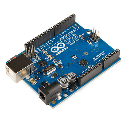
This Arduino nonsense is actually pretty neat. It’s a small electronics project board with a programmable chip and a pile of General Purpose I/O pins. You can use it to control or be controlled by pretty much anything. There’s tonnes of examples out there from the simple blinking an LED to the much more complex task of automating the watering and lighting of indoor grows. The best of it is this thing costs £5 – five pounds sterling, no shit!
Unless I’m horribly mistaken but £5 is also the cost of a lego style knife, fork and spoon set.

Don’t get me wrong these are pretty cool too but you can’t program it to electrocute your mate whenever he gets a quiz question wrong so why bother – get an Arduino instead 🙂
Lets take a look at ‘my first Arduino projects’ or at least ones I’ve managed to get working today…
First up we have a PIR sensor in action. This little add-on isn’t free but it was only £2 from fleabay. It’s amusingly also sold as a ‘human detector’ but in fact PIR is Passive InfraRed, meaning it will trigger whenever it sees heat movement – such a cat or a dog or a hamster or a human.
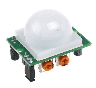
These tiny little things (about the size of a 50p piece) are dead easy to get working. All you need is the sensor, an LED, a resistor and a breadboard.
Here’s the wiring diagram.
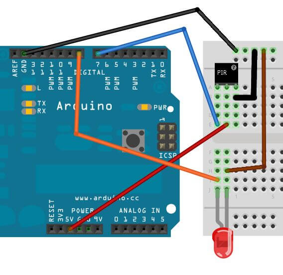
Yes I am too lazy to make my own but that is all correct except the pin outs on the PIR didn’t match mine. Pins 1 & 3 should be switched round – if in doubt they are marked on the PCB so worth checking. The only other thing is there’s no resistor for the LED. I put a 300Ohm between ground on the LED and ground on the Arduino just in case.
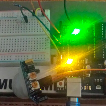
Here’s the picture of the one I cobbled together for real. Now you know why I don’t often use images I’ve taken myself.
To make life even easier, after all this is just an example to see it working, there’s some pre-written code to rip off too.
Simply open up the Arduino IDE and paste in the code from here.
Here’s a quick explanation to what is going on so it’s not just a copy/paste exercise.
int pirPin = 7;
int ledPin = 8;
These numbers correspond to the pin outs on the Arduino which are in the diagram above. Your LED is plugged into pin 8 and your PIR sensor’s ‘Out’ pin is connected to pin 7 on the Arduino.
This means we are reading a voltage from the PIR sensor and sending a voltage out to the LED to make it light up.
  Serial.print("calibrating sensor ");
    for(int i = 0; i < calibrationTime; i++){
      Serial.print(".");
      delay(1000);
      }
    Serial.println(" done");
    Serial.println("SENSOR ACTIVE");
    delay(50);
  }
This code here is a fancy way of saying ‘wait 10 seconds for the sensor to become ready’ the code itself is not calibrating anything.
This next snippet is enough to see what is happening.
void loop(){

     if(digitalRead(pirPin) == HIGH){
       digitalWrite(ledPin, HIGH);   //the led visualizes the sensors output pin state
We see a ‘digitalRead’ from the PIR output and compare it to ‘HIGH’ – this is another way of saying ‘is there voltage on the pin’ and if so then do the next line. The next line happens to be a ‘digitalWrite’ to the pin the LED is connected to – it makes it HIGH, or in other words turns a voltage on to make the LED light up.
This is a nice example of using an external sensor to make something visual happen. You can wave your hand in front of the PIR sensor and the LED lights up – great stuff.
That was a nice example to make sure I understood what was going on – next up is getting the Raspberry Pi to send the Arduino some data. The idea is the Pi can then control the Arduino but let the Arduino handle the external electronicals.
The second project of the day ‘Nagios LED’ can be found here.