A simple and quick project for detecting when a Yaesu transciever is transmitting and feed that status to Home Assistant to then perform actions. This can be used to, for example, automate killing the power if the radio gets stuck TX’ing when using automated digital modes software such as WSJT-X remotely. It can also measure the supply voltage, which is always useful information to know, especially when operating remotely.
What you need for this project:
- Working Home Assistant installation (https://www.home-assistant.io/)
- Working MQTT broker (http://mosquitto.org/)
- WeMos D1 Mini board (https://www.wemos.cc/en/latest/d1/d1_mini.html)
- Regulated 5VDC buck converter (14VDC in 5VDC out is perfect)
- Tasmota or ESPHome installed on said D1 mini (https://tasmota.github.io/docs/ or https://esphome.io/)
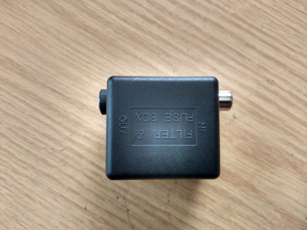
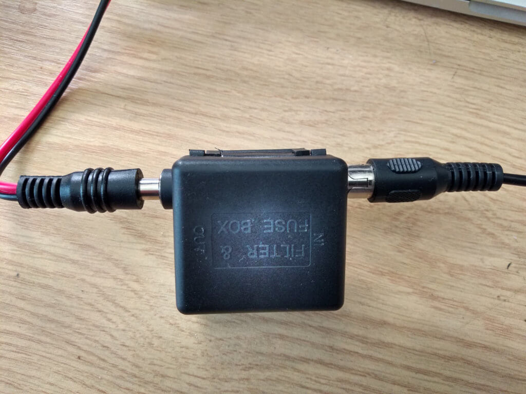
- Small project box (I used a fusebox)
- Phono socket / phono cable
- DC Barrel jack and socket
- 10k ohm resistor (for TX sense)
- 270k ohm and 68k ohm resistors (for voltage sense)
- CAT (DIN) cable or phono cable (depending on tranciever model)
Total cost of parts: £15-£20
When I said a ‘simple’ project let’s first clarify this is simple when you already have a working Home Assistant with MQTT instance and familar with flashing and configuring software like Tasmota or ESPHome onto ESP8266 boards (https://github.com/tasmota/tasmotizer is one way). I’m not going into details of Tasmota and the MQTT messaging bus – there is a tonne of information on the Internet about this.
How does it work?
When a Yaesu radio (I know this works with the 857, 897, FTDX10 and FTDX101) goes into transmit mode it bridges the TX GND pin to GND in the CAT port (in the case of the DX series it has a dedicated phono port). This is extremely reliable and it doesn’t matter what triggers the TX – could be the microphone PTT, VOX or when working with digital modes.
All we need to do is detect when the pins are shorted and use that to trigger an MQTT message which is picked up by Home Assistant. We can use a digital pin on an ESP8266 to detect when this happens by feeding 3.3v into the pin to make it logic high and grounding it to make it logic low. This state change is read by Tasmota.
Once the state is known by HA we can trigger automations, in this case it will tell the switch the radio’s PSU is plugged into to turn off if the radio has been TX’ing constantly for more than 15 minutes – thus instantly killing power to the radio. A very nice safety net when the radio is running unattended.
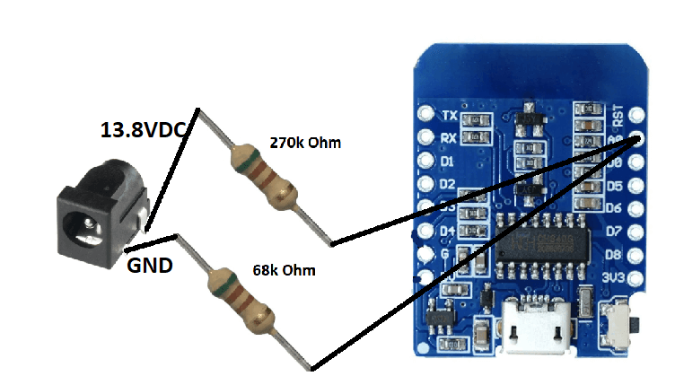
The voltage sense feature uses a voltage divider to drop the input voltage down to less than 3.3VDC, which is the maximum the A0 (analogue ADC) pin on the D1 Mini can handle. The ESP8266 chip itself can actually only handle 0-1VDC but the D1 board has a divider built in to bring that up to 3.3VDC. However, as we want to measure up to something like 16VDC we add another divider.
Circuit Diagram
The detection circuit couldn’t be any simpler. Essentially we hold a digital pin high using a 10k pull up resistor and then short it to GND when the radio transmits.
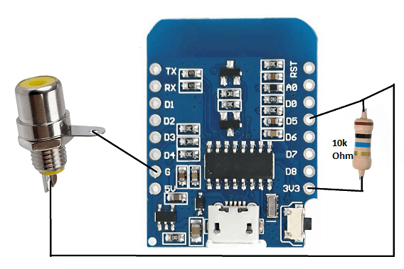
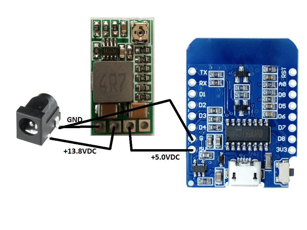
We can power the D1 Mini from the same PSU as the radio using a 5VDC regulated buck converter. Wired as follows:
The voltage divider should be wired as follows:
The CAT port pin out of the 857/897 is as follows.
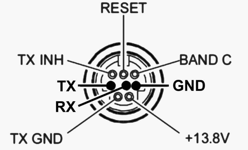
We are interested in the TX GND and GND pins. Those two pins should be connected to a phono cable using whatever method you see fit. GND should be connected to the outer sleeve of the phono plug and TX GND to the inner. You can test you have the correct pins by using a multimeter in continuity mode. When you TX the meter should beep.
For the FTDX10 and FTDX101 use the dedicated TX GND port instead. As this is a phono socket it means an off the shelf audio cable can be used to hook it into this module.
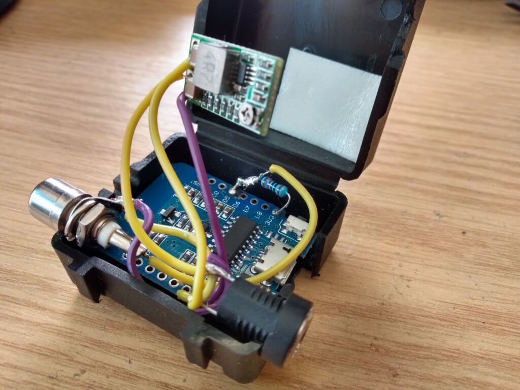
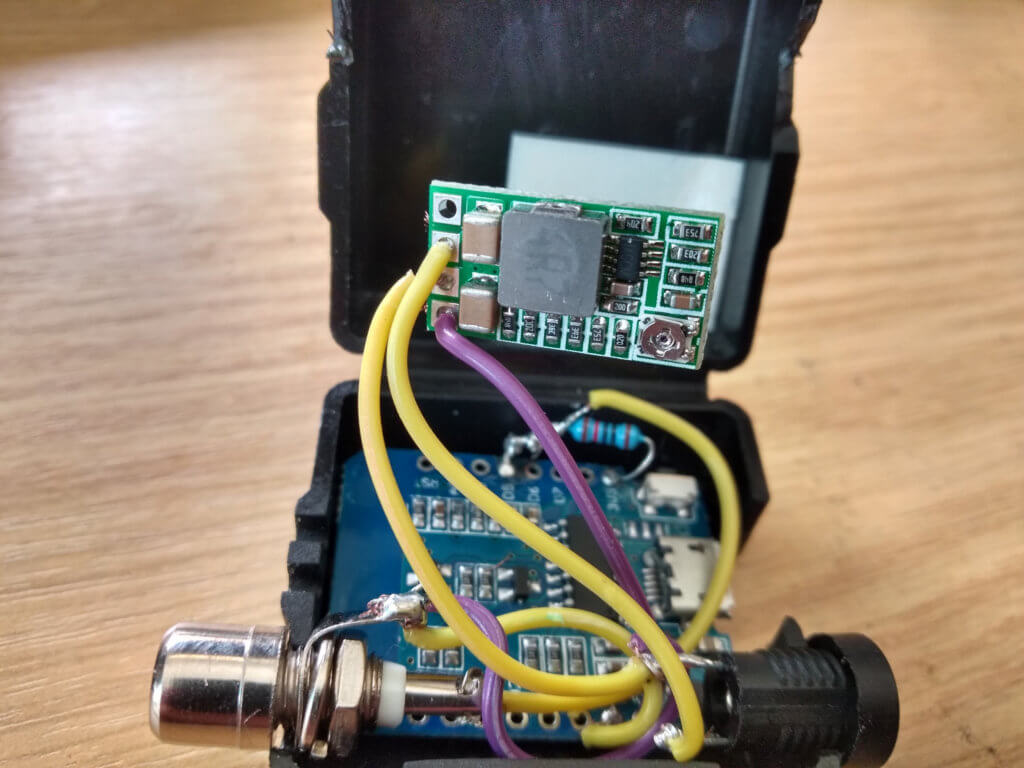
Here’s how it might look once assembled. These photos don’t show the voltage divider.
Tasmota / ESPHome
You’ll need to download and write Tasmota or ESPHome to the D1 Mini. There is plenty of info on the Internet how to do this. Once written to the board you’ll need to configure it to join your WiFi.
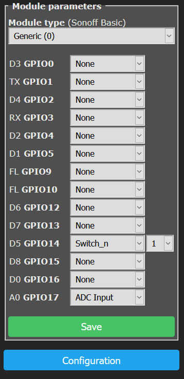
For Tasmota, assuming you can now access the web interface navigate to Configuration -> Configure Module. Set the module type to ‘Generic’. It should automatically reboot.
Navigate to the same section and now set ‘D5 GPIO14’ to be ‘Switch_n’ and ‘A0 GPIO17’ to be ‘ADC Input’ as per this screenshot.
Next configure the MQTT settings in Tasmota as you would for any other device.
For ESPHome you’ll similarly need to configure a sensor on D5.
Once that’s all done you are ready to test if it works.
First, plug the CAT cable into the radio and the phono cable into the socket then fire the radio up. Open the ‘Console’ in Tasmota and keep an eye on the log. Press and release the PTT on the radio a few times and you should see the following POWER related messages appear in the logs.
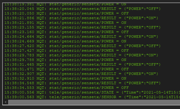
When the radio is in TX the state will be ON and when RX it will be OFF. The MQTT stat path will be used in the HA configuration.
In order to increase how often the voltage is reported, execute the following command in the same console:
TelePeriod 10This will mean Tasmota reports the voltage every 10 seconds, which is ample for this purpose. You should see these updates as follows, note the value for ‘A0’ – this will be between 0 and 1023, with around 720 being 13.8V.

Note: When the D1 Mini boots up the radio must be in RX state otherwise the logic will be reversed whereby TX will be reported as OFF rather than ON. If this occurs simply reboot the device whilst the radio is in RX. The reason this occurs is because Tasmota reads the state of each pin when it starts and assumes that is the default state.
Home Assistant
The configuration within HA is nice and straight forward. Here is an example configuraion for the sensor (in my case I have all sensors in sensors.yaml). Note ‘sensetx’ is the device name set in Tasmota.
- platform: mqtt
name: "Yaesu TX"
state_topic: "stat/generic/sensetx/POWER"
icon: mdi:antenna
- platform: mqtt
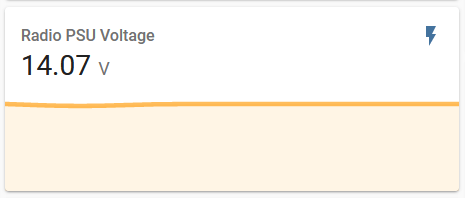
name: "Radio PSU Voltage"
state_topic: "tele/generic/sensetx/SENSOR"
value_template: "{{ (value_json.ANALOG.A0 | float / 51.3) | round(1) }}"
unit_of_measurement: "V"
device_class: powerNotice the division by 51.3. This is calculated and acts like a calibration for the ADC. We round to one decimal place as the ADC isn’t accurate enough at these levels and the margin of error will mean it flaps constantly. In order to work out what value you should use for the division I suggest doing the following:
First, set your PSU to 13.8V and measure this with an accurate multimeter to ensure it reads true. Next, read the value being reported for ‘A0’ in the Tasmota console (as described above). Now all you do is divide the A0 value by the voltage on the multimeter to give you the number you need to divide by in the sensor value template.
An example automation looks like this. This will cut the power after 15 minutes of continuous transmitting. In this case I have the radio’s PSU plugged into a switch (SONOFF running Tasmota), which is also controlled by HA.
- id: '8000001'
  alias: 'Turn off radio if tx for too long'
  trigger:
      platform: state
      entity_id: sensor.yaesu_tx
      to: 'ON'
      for:
        minutes: 15
  action:
    - service: switch.turn_off
      data:
         entity_id: switch.radio
Another example which will kill the power to the PSU if the output voltage is too high.
- id: '8000008'
  alias: 'Turn off PSU if voltage too high'
  trigger:
    - platform: numeric_state
      entity_id: sensor.radio_psu_voltage
      above: 14.30
  action:
    - service: switch.turn_off
      data:
         entity_id: switch.radio
You can also create a counter to show how long it has been in TX state for. You need two more automations.
- id: '8000005'
  alias: 'Yaesu TX Timer Increment'
  initial_state: on
  trigger:
    platform: time_pattern     # every 1 second
    seconds: '/1'
  condition:
    condition: state
    entity_id: sensor.yaesu_tx
    state: 'ON'
  action:
  - service: counter.increment    # increment the counter by 1
    data:
      entity_id: counter.yaesu_tx_counter

- id: '8000006'
  alias: 'Yaesu TX Timer Reset'
  initial_state: on
  trigger:
      platform: state
      entity_id: sensor.yaesu_tx
      to: 'OFF'
  action:
  - service: counter.reset
    data:
      entity_id: counter.yaesu_tx_counter
And the counter object itself.
counter:
yaesu_tx_counter:
name: 'Yaesu TX Time'
icon: mdi:timer-outline
initial: 0
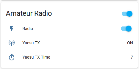
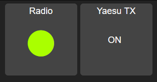
step: 1Here is how it looks in the interface.
You could also create a basic dashboard for it using Appdaemon:
Improvements
An improvement could be to power the module from the 13.8v ouput present on the CAT port of the radio – it can provide more than enough current. This would be a rather slick as it means you could have a single DIN cable from the radio to the module.
The ADC in the ESP8266 is only 10bits and reads 0-1VDC – that’s 1024 different values. This means for our purposes the voltage accuracy is 0.02VDC. This isn’t very accurate really. It also becomes less linear as it approaches 0VDC and suffers from noise issues. This isn’t a big issue for this use case as we’re more interested in the higher values and not after precision. However, you could use something like an ADS1115 board, which has 16bit resolution, four ADCs and a Programmable Gain Amplifier. It uses the I2C bus and allows for up to 4 addresses, meaning you could run 4 of these on one ESP8266 giving you 16 ADCs total. I don’t think that would work with Tasmota but certainly does with ESPHome. See this page for more information. They cost around £3.50.
Have Fun!
Hopefully this gives someone inspiration to think of other neat solutions. You can of course use the sensor itself with anything which bridges the phono plug contacts together, such as an old door bell button.