For my next trick I thought it would be nice to have a web interface “colour wheel” to control an RGB LED strip light. These are dirt cheap and usually come with a crappy infrared remote control. The real nice part about this is once you have it working you can do almost anything you want with it – make a gradual sunrise light for the dark mornings, a security light, an auto-off night light or simply pick the colour you want your room to be from a smart phone.
The basic idea of this design is to have the Arduino handle the control of the LED strip itself but allow the RGB values to be set via a serial connection. The Pi will be sending the RGB values via USB to the Arduino which in turn will use Pulse Width Modulation (PWM) to set the intensity of each LED.
The total cost (minus the Pi and Arduino) is £11.50 – the result is a 5 meter internet controllable strip light, what’s not to like about that?! Lets have a look at how it’s done.
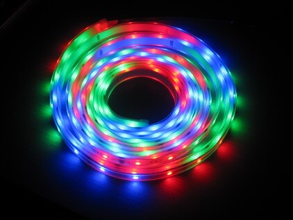
First up we need an RGB, non-addressable LED strip. These are cheap and cheerful like this one from Amazon. £10 is about the right price.
Secondly we need some MOSFET transistors – three to be exact, one for each colour. There are many to choose from but I quite like the STP16NF06‘s which can be gotten from here. These are cheap N-Channel MOSFET’s rated at 16A which means you can run between 750 – 1500 LED’s with them – that’s a shit load. Paying £1.50 for all three is about the right price.
Here’s the internals of our chosen MOSFET. We need to know the pins for the Drain, Gate & Source.

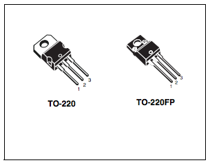
We can see that Source is pin 3, Gate is pin 1 which means Drain must be pin 2. The body is usually connected to the Source, meaning it is a 3 pole device. The ‘Gate’ is what is used to turn on and off the internal switch. A transistor is pretty much just a switch/relay which can turn on and off very quickly. By applying a voltage to the Gate it makes it close which in turn allows current to flow from the Source to the Drain. The Source is connected to our high voltage/high current power supply and the Drain is connected to the LED strip.
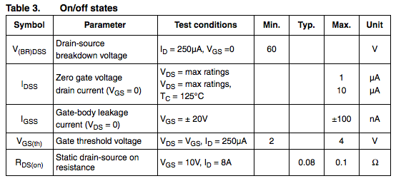
In order to operate the Gate a transistor has a minimum required voltage (Gate threshold voltage). For this transistor we can see that is 2V, which is plenty low enough for the Arduino.
Now we have enough information to know this should work and how to wire it up. Here is the breadboard layout, courtesy of Adafruit.
You can see that transistor pin 3 (Source) is attached to Ground of the Arduino. This is because we are using the transistors to control the flow of pixies back to ground, as opposed to via the 12V positive input.
This is important: The Arduino will not have enough oomph to power the LED strip by itself (via USB). Thankfully it has a useful feature – the grey connection in the diagram should actually be connected to the ‘Vin’ connection on the Arduino and the PSU which came with the LED strip should be plugged into the Arduino’s power input socket. What now happens is Vin will be +12V and, providing you are not powering >1A’s worth of LED’s, the Arduino can transfer enough power straight to the LED strip (it has a 4007 diode across Vin meaning 1A max forward current). If you are using lots of LEDs you need to connect the positive of the PSU directly to the LED strip and ground to the MOSFETs but remember to make ground common between the PSU and the Arduino.
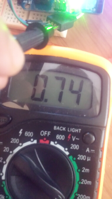
A typical 5m strip will consume 0.75 Amps at full power (#FFFFFF/255,255,255/full brightness white) as you can see here. For most colour combinations it averages around 0.5A, which means you could possibly run two strips via the on board power connector but I wouldn’t risk it.
Before continuing with the code side of things lets quickly look at how this is going to work. We are using the PWM capable pins on the Arduino to control the brightness of each LED. Pulse Width Modulation works by switching the voltage on and off at different rates to achieve an overall average voltage. In this case by switching the gate of the transistor on and off at varying frequency the LEDs ‘see’ either a lower average voltage for dim or higher average voltage for bright.
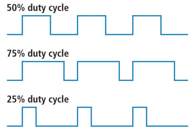
We can see that in order to achieve half voltage the signal is off 50% of the time and on 50% of the time. For 25% it is on 25% of the time and off 75% of the time. In other words if the input voltage is 10V and we want 7.5V average output we would need the signal to be on 75% of the time, or 75% duty cycle.
The Arduino allows PWM to be controlled from the values 0-255 (255 = 28 – 1) meaning we have 8bit PWM control. That is more than granular enough for controlling the brightness of an LED.
Now the code itself. First up the Arduino code. This is based on code by Tom Igoe.
// pins for the LEDs:
const int redPin = 5;
const int greenPin = 6;
const int bluePin = 3;

void setup() {
  // initialize serial:
  Serial.begin(9600);
  // make the pins outputs:
  pinMode(redPin, OUTPUT);
  pinMode(greenPin, OUTPUT);
  pinMode(bluePin, OUTPUT);

}

void loop() {
  // if there's any serial available, read it:
  while (Serial.available() > 0) {

    // look for the next valid integer in the incoming serial stream:
    int red = Serial.parseInt();
    // do it again:
    int green = Serial.parseInt();
    // do it again:
    int blue = Serial.parseInt();

    // look for the newline. That's the end of your
    // sentence:
    if (Serial.read() == 'C') {
      // constrain the values to 0 - 255
      // if you're using a common-cathode LED, just use "constrain(color, 0, 255);"
      red = constrain(red, 0, 255);
      green = constrain(green, 0, 255);
      blue = constrain(blue, 0, 255);

      // fade the red, green, and blue legs of the LED:
      analogWrite(redPin, red);
      analogWrite(greenPin, green);
      analogWrite(bluePin, blue);

      // print the three numbers in one string as hexadecimal:
      Serial.print(red, HEX);
      Serial.print(green, HEX);
      Serial.println(blue, HEX);
    }
  }
}
It’s fairly self explanatory what is going on.
- Reads the RGB integer values from the serial port (ending in the letter ‘C’)
- Sets these values on the PWM outputs
- Writes the Hex equivalent value back to the serial port.
What is really handy is RGB values are also 8bit. We know that our PWM control is 8bit so put two and two together and we have a perfectly matched system for controlling our LEDs without the need for any fancy conversion. A quick outline of how this looks.

Say we want our LED strip to be pure red. The RGB values would be ‘255,0,0’. If we wanted blue it would be ‘0,0,255’ and if we wanted yellow it would be ‘255,255,0’, it’s as simple as that.
Next we connect our Arduino to our Pi via USB. This automatically sets up serial communication between the two because the Arduino has a USB to serial chip in it and the Pi will magically have the drivers for it. Once plugged in we will have a serial device named /dev/ttyACM0
Because we set our ‘end of sentence’ character to be the letter ‘C’ we can do a quick test with this:
cat /dev/ttyACM0 &
echo -n '255,0,0C' > /dev/ttyACM0
We should now have all the red LEDs on our strip lit up nice and bright. In addition you should see the Hex value returned in the terminal (because ‘cat’ is running in the background, outputting to stdout). In this example it will be ‘#FF0000’.
Word of warning here. ‘cat’ is required to prevent the Arduino from triggering a serial port reset. How that works is for another article.
Now we know that works we can do some useful stuff. The title of this article was to have an Internet controllable LED strip so we need some kind of front end for this. What better front end than the humble web browser. Time for some HTML/JS/PHP.
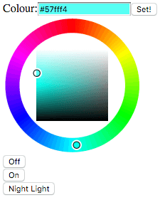
First up is a nice colour wheel. For this we are going to use farbtastic. Go ahead and download/extract that into your web root. In addition you will also need the jQuery .js file from jquery.com – version 2.x does the job nicely. Rename it ‘query.js’ and put it in the same directory as farbtastic.
Next we need a quick script / form stuff for the main page. Grab index.php and place it in the web root.
To make this useful we need something to do the processing. For this we will use PHP. She ain’t pretty but she’ll do the job. Grab submit.php and put it in your web root. This does a couple of things.
$serial = fopen("/dev/ttyACM0", "w")
It’s going to write straight to the serial port. For this the web server needs permission to do so, therefore add ‘www-data’ to the ‘dialout’ group (‘adduser www-data dialout’).
It also write two files, /tmp/led-last-colour-hex and /tmp/led-last-colour. These hold the Hex and RGB values of the last colour to be set.
You will also notice it has a ‘Night Light’ button which will turn on a gentle blue colour. This could be left on all night or timed to turn off at say 1am using cron:
00 01 * * * /bin/echo -n '0,0,0C' > /dev/ttyACM0
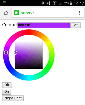
Voila! We now have a web interface for our LED strip light. It even works on a mobile phone.
Because we now have the LED’s controllable over serial we can do almost anything we want. Here’s a quick example of how to make a sunrise light – this is where the brightness of the LEDs increases slowly over time to simulate sun rise. It’s been shown to help getting up during the winter months when it’s still dark outside.
#!/bin/bash
i=0
while [ $i -lt 255 ]
do
 let i++
 echo "$i,$i,$i"C
 echo -n "$i,$i,$i"C > /dev/ttyACM0
 sleep 7
done
echo "0,0,0C" > /dev/ttyACM0
That will take 30 minutes to go from off to full power white and then turn off again. You could schedule it with cron to start at 07.00am on every weekday.
00 07 * * 1-5 /home/scripts/sunrise.sh > /dev/null
We could also use the LED strip to change colour and blink with Nagios alerts and then revert back to the previous known colour when it recovers. This uses the /tmp/led-last-colour files from the web interface to restore the previous colour.
#!/bin/bash
if [ ! -f /tmp/led-last-colour ]
	then
		echo "Warning: Cannot find last colour file"
fi

function get-status {
   if [ ! -f /var/cache/nagios3/status.dat ]
      then
	   echo "Status file not found! Setting STATUS = 2"
	   STATUS=2
      else
        STATUS=$(grep current_state /var/cache/nagios3/status.dat |sort -rn |uniq |awk -F '=' {'print $2'} |head -n1)
   fi
}

function blink {
	let i=0
	while [ $i -lt 30 ]
	   do
		let i++
		echo -n "$1"C > /dev/ttyACM0
		sleep 1
		echo -n "0,0,0"C > /dev/ttyACM0
		sleep 1
	done
}

function check-status {
	if [ "$STATUS" -eq "0" ]
        	then
                	if [ $CHANGED -eq 1 ]
                                then
                                        LAST=$(cat /tmp/led-last-colour)
					if [ -z "$LAST" ]
						then
							LAST="0,0,0"
					fi
                                        echo -n "$LAST"C > /dev/ttyACM0
					CHANGED=0
					echo "OK - Last: $LAST"
			else
				echo "OK"
                	fi

        elif [ "$STATUS" -eq "1" ]
                then
			CHANGED=1
			echo "WARN"
                        blink "255,255,0"
        else
		CHANGED=1
		echo "CRIT"
                blink "255,0,0"
	fi
}


CHANGED=0

while true ; do

get-status
check-status

if [ "$STATUS" -eq "0" ]
	then
		echo "long wait"
		sleep 300
	else
		get-status
		check-status
fi
done
It’s worth remembering that in order to send serial data to the Arduino you must have /dev/ACM0 remaining open. You can do this with a crude while loop.
#!/bin/bash
while true
  do
	cat /dev/ttyACM0 > /dev/null
	sleep 1
done
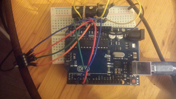
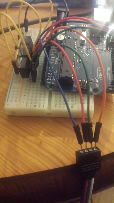
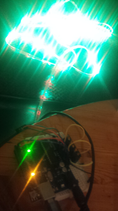
Have fun finding more uses for this but at least this gives some practical examples 🙂 Here are some of my build pics.


Are you sure that the internal schematic diagram is correct?
Yes it should be, as per http://www.st.com/web/en/resource/technical/document/datasheet/CD00002501.pdf